Category Archives: Cloud Lidar Technology

Ceilometers and Snow

Like Rain, Snow produces quite high levels of backscatter.   But the raindrops and snow flakes have very different shapes, velocities and surface area to mass ratios.  More expensive ceilometers may have the ability to discriminate between snow and rain.

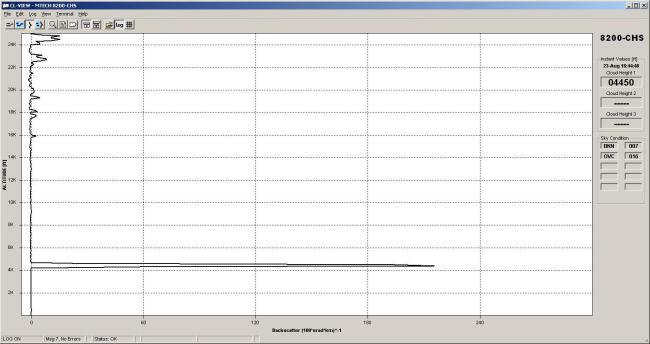
A typical LIDAR curtain plot for cloud appears below:

snow plot

Ref: University of Utah Atmospheric Science

The snow is coming from a cloud at around 500m .  The cloud and snow appear to extinguish the returns from higher layers,  if any.   Some of the snow is light and evaporates before it gets to ground level.  ( low level green return )

Work has been done to try to determine snowfall rate from Lidar returns.  According to Ed Eloranta of the University of Wisconsin Madison,  the technique requires radar and  does not require any knowledge of the snowflake shape.

Download Poster

Click to access arm_09.pdf


Single Lens vs Dual Lens Ceilometer

All ceilometers which are set up for  long range cloud height measurement are “far sighted”,  having a blind region in front of the unit.  This is shown in the diagram below ,  and the height of the blind spot Rio is heavily dependent on the axial separation d ,  the beam divergence and the telescope angle of acceptance.  The signal is maximised at the full overlap distance Rovf as shown below.

dual overlap

Since most ceilometers are designed for the best acheivable  signal to noise ratio,  the telescope angle of acceptance is set to the limit of  focal length,  sensor active area and lens aberration.

The single lens designs,  such as the CL51 and 8200-CHS feature a low  value of d and thus a much reduced overlap height

Single lens overlap geometry

There are a number of different optical arrangements to enable the reduction of d to zero or to a small value to minimise the overlap height.

One form of “single lens” Ceilometer,  using a “split lens ” approach (reference (Vande Hey, J. ;  Coupland, J. ; Richards, J. ; Sandford, A. )

It is worth noting that earlier designs of dual lens ceilometers actually utilised the blind spot to reduce the required dynamic range to prevent overload of the return signal processing channel, and greatly reduce optical  crosstalk in the instrument itself ( known as To crosstalk)

Later ceilometers using the single lens optics,  such as the MTECH SYSTEMS  8200-CHS feature special techniques to minimise optical crosstalk and very high dynamic range analog to digital converters to enable detection of fog close to the ground without saturation of the signal

Ceilometer Laser Safety.

Ceilometers must be eye safe and meet Class or Class 1m  Laser Safety standard under the international specification IEC 60825-1  or ANSI Z136 in the USA

The phrase “eye-safe” is used below.

Class 1:   This class is eye-safe under all operating conditions.

Class 1M:  This class is safe for viewing directly with the naked eye, but may be hazardous to view with the aid of optical instruments. In general, the use of magnifying glasses increases the hazard from a widely-diverging beam (eg LEDs and bare laser diodes), and binoculars or telescopes increase the hazard from a wide, collimated beam   Radiation in classes 1 and 1M can be visible, invisible or both.

The beam from a ceilometer has a very low divergence,  which is mainly determined  by the finite size of the laser source and the ceilometer lens/mirror focal length,  but can also be effected by spherical aberration and diffraction effects in the optical path in the instrument.

Wikipedia Entry: Laser Safety

Sky Condition, How is it assessed ?

A human observer looks at the sky and estimates the coverage in 8ths ,  0 being clear sky and 8 being overcast.   The human observer then estimates cloud height and applies these estimates of cover for each layer.    It is quite obvious that if there are no breaks in the sky,  any higher layers present cannot be estimated.    The human observer also suffers from the “packing” effect of an oblique line of sight , and usually tends to overestimate cover.

For each layer the human observer will give the condition FEW,  SCATTER,  BROKEN AND overcast.

A ceilometer can only “see” cloud above it,  so can only estimate the sky condition by analysing heights over a time period.

The Sky Condition Algorithm in the 8200-CHS  is based on that developed by the US National Weather Service and used in their automated surface observing system (ASOS) units and  guidelines published by the World Meteorological Organization.

A study by the Hughes STX Corp. found that when ceilings were under 5,000 feet, this algorithm agreed with the human observer 78% of the time. With fog, the comparability was 84%, with rain it was 69%, and when snowing 74%. During rain, the NWS Algorithm reported more changes than the human observer.

However at the transition between scattered and broken cloud coverage 4 oktas humans often report too much cloud coverage. This is attributed to the “packing effect;” a condition where an observer does not see the openings in the cloud decks near the horizon due to the viewing angle.   Pilots tend to overestimate the coverage even more than ground observers because of visual compression.

The 8200-CHS algorithm is not biased by the “packing effect” because it measures only the sky conditions passing over the sensor

Details of the 8200-CHS specifications can be found here 8200-CHS Page

Why tilt a ceilometer?

A slight tilting of the ceilometer gives  better performance in rain.

Rain drops tend to flatten as they fall.  See the NASA explanation for this 

Consequently, when aligned vertically the backscatter from raindrops may be sufficiently high to cause difficult in resolving the cloud base above the rain.

However when tilted, the backscatter of laser pulses by the raindrops is reduced .

In heavy rain even a tilted ceilometer cannot resolve the cloud base since the integrated backscatter quickly dominates and prevents further penetration up to the cloudbase,  while extinction in the return path also starts to extinguish the return signal..

Please refer to the screen below.

8200-tilted-untilted

These tests were carried out during light rain.  The tilted unit shows resolvable cloud base while the untilted unit reverts to vertical visibility.

Ceilometer Signal to Noise.

There are a great many factors effecting the performance of ceilometers,  but the key 2 issues for any given cloud volume backscatter coefficient  are:

  1. The eye safe limit of the ceilometer .  Infra Red Ceilometers must operate as Class 1M lasers  which limits the energy density of the beam.
  2. The noise level.      The inherent noise level of the ceilometer is the ultimate determinant of the signal to noise ratio which enables the ceilometer to discriminate  cloud boundary.

The 8200-CHS has an extremely low level of inherent noise,   which is tested for each ceilometer and is recorded as per the backscatter profile below.

8200-CHS MAIN CARD OC NOISE

The external source of noise is the shot noise of the scattered and or direct solar radiation within the spectral acceptance of the sensor .   The laser operates around 910 nm and the filtering can only limit the “out of  band”  component of the solar noise spectrum.  The ceilometer will thus t\detect cloud at higher altitudes at night.

Calibrating a Ceilometer

There are 2 types of calibration.

  1.  Calibrating the distance measurement:  In this case the ceilometer is turned on its side and aimed at a hard target.    In this case the ceilometer is aimed at a tree 4450 ft away.   The exact distance of the tree was surveyed using Google Earth.  The ceilometer was aimed using a telescopic sight.    The backscatter profile is an almost perfect replica of the laser pulse,  delayed by the time taken for the laser pulse to go to the target and back.

8200-CHS HARD TARGET AT 4450

In reality,  the calibration of the ceilometer is based on the well known speed of light and if the timing crystal inside the ceilometer is accurate and stable,  the distance calibration is stable and accurate and should never need to be checked in the service life of the ceilometer.

Clouds are not solid reflectors,  and the backscatter comes from a range of scatterers inside the cloud,  so the backscattered laser pulse is broadened and flattened.   The height of the cloud is defined as a threshold in the  backscatter profile which has been determined will result in a correct reading for most types of cloud.

2.   Calibrating the ceilometer  constant.    For this ,  there is a clever method as described in a paper by O’connor  et al,  which utilises the known Lidar Ratio of 18.8 in stratocumulus cloud ( SC).

A technique for autocalibration of cloud lidar

8200-CHS Ceilometer multi level clouds

The 8200-CHS has the capability of detecting up to 4 simultaneous layers but certain types of standard messages display only 3 layers .

If the lowest layer is optically dense,  the returns from beyond the first  layer are extinguished ,  and the layers above it are not detected until a gap in the lower layer is detected.   If the cloud is not optically dense,  the return from a higher level cloud is not significantly attenuated when passing back through the lower layer,  so both layers can be detected.

Here is a case where multiple layers are  at 6620 and 7290 are both detected.